My latest apartment doesn’t have a thermometer in it. So, like any good hacker, rather than buy a thermometer, why not build one? 7 segment LED displays can show one digit, but working with them can be a bit tricky. In this post, I’ll show you how to setup a single digit display with an 74HC595N shift register.
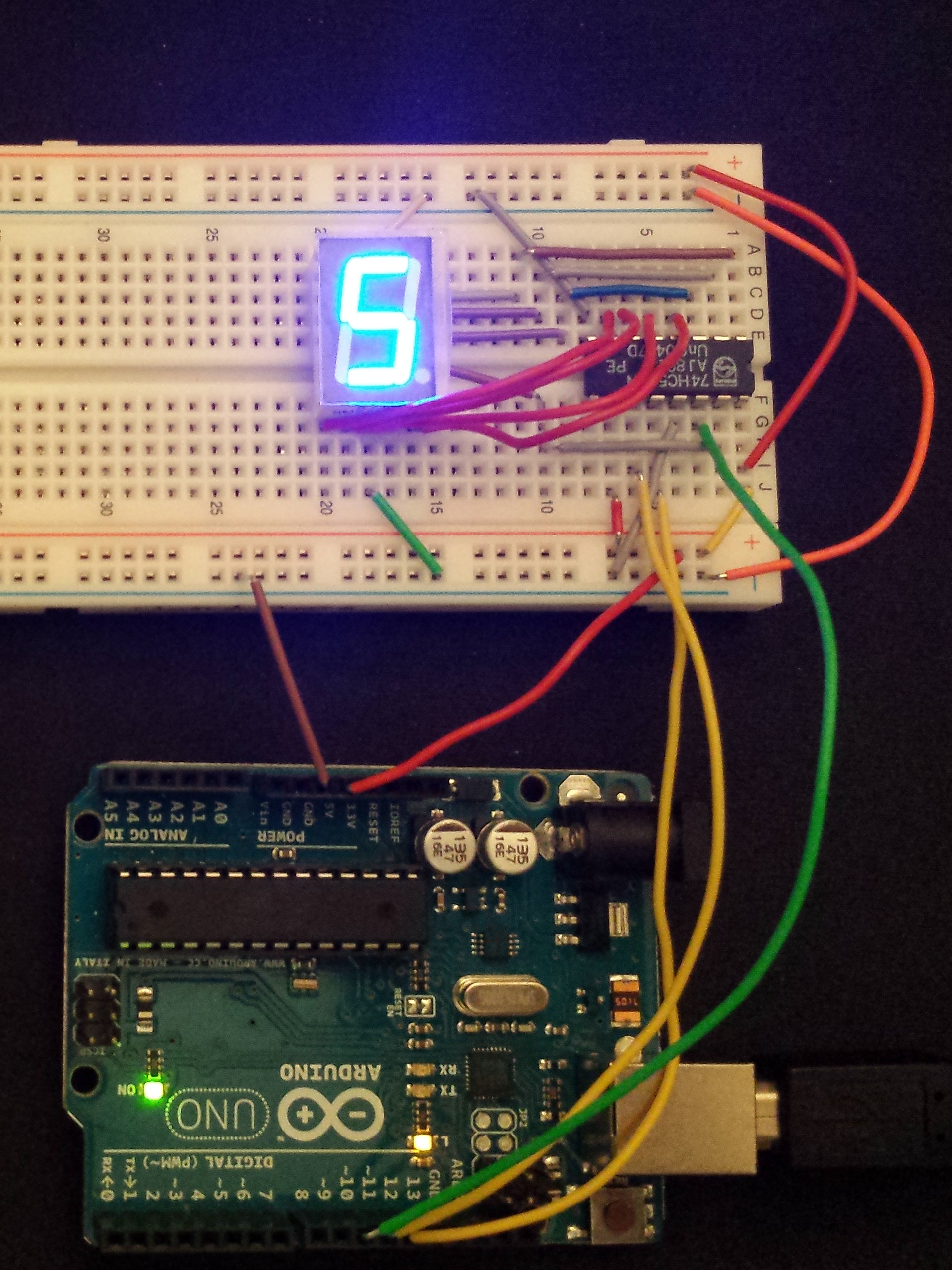
Arduino Uno connected to a 7 segment LED display through a shift register.
Before we begin:
The key components needed for this project are the following:
- Arduino Uno
- 74HC595N Shift Register
- 7 Segment LED (Microtivity IS131 Common Cathode)
- Jumper Wires
- USB Cable
Software for this post can be found here.
Code Explanation:
I’ll leave the finer points of the different components out, but the sketch is generally represented by the following points. First, the pins are configured to connect to the shift register (10,11,12 in my case). The main loop simply writes one digit to the LED display every half a second. It is essentially a counter in this sketch. Updating the LED display is done in the updateLEDs function. There, the process of sending the data to the shift register is done in three steps.
- Low Latch
- Write the 8-bits out to the register (7 number segments and a dot.)
- High Latch
Mapping Shift Register to LCD:
The main challenge that I faced in this quick project is how the shift register maps to the 7 segment LED. While you can certainly try and work through trial and error, I made the following notes to translate from the pin out to the actual integer that I needed to specify the bit string to send from the Arduino.
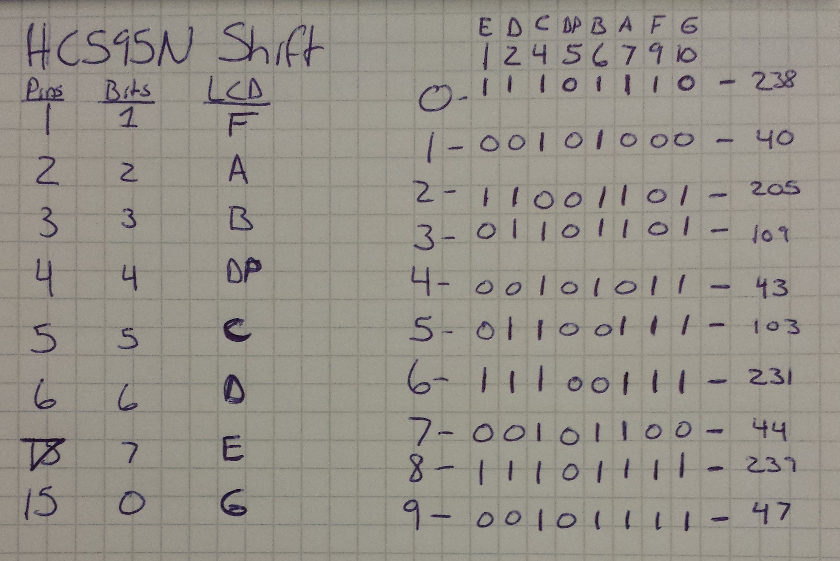
Notes I jotted down to figure out what pins connected to the LED display and what bits to turn on.
First, I noted the pins on the shift register that actually go out to the LED (1-7,15). Next, I figured out the bit position for each pin (Second column, with 0 on the right and 7 on the left). Finally, my LED came with a diagram showing how the pins on the LED mapped to the outputs on the front. They map those with the letters A-G.
To figure out the actual integer values that I needed to specify a digit, I made the table on the right. Here, I first wrote the digit on the left, then I wrote the pin for the LED and the letter it represented on the top. For each digit, I figured out which segments needed to be on and filled those with 1s. 0s mean the segment is turned off. To complete it, I translated the bit strings to their integer representation, which are represented in the sketch by the variable seven_seg_ints_rev.
That’s all there is to it. Connecting the hardware isn’t too hard. I found translating from the shift register pins to the LED to take the most time. I’d estimate it took about 1.5 hours from start to finish. Good luck!