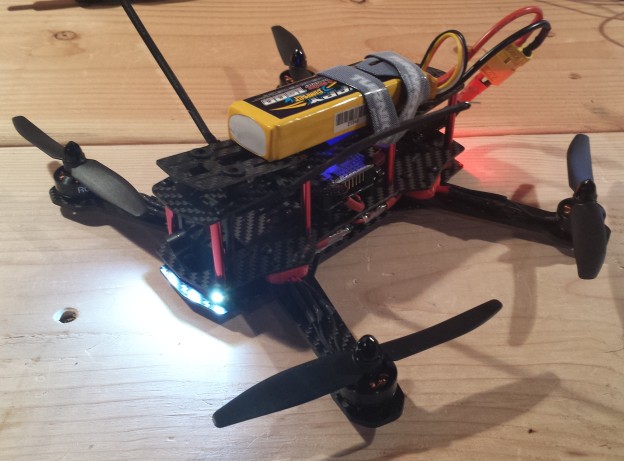

The finished ZMR250 build without FPV gear hooked up.
The ZMR250 is a quadcopter frame in the 250mm size class. Compared to the popular DJI Phantom, the platform is significantly smaller, lighter and intended as a racing quad. After starting out with my RCExplorer Tricopter V2 build a few years ago, I kept my eye out for a quadcopter that could easily be packed inside a briefcase for portability. Being small and fast, the ZMR250 excels as an FPV platform for low, fast flying in an affordable and surprisingly durable platform. In the following post, I detail a few key lessons I learned and an overview of my hardware choices.
Research is Key:
I can’t stress this enough when building custom multirotors. Do your homework by checking out forum threads for similar quad builds to get a good idea of the common components and layouts. For this build, I read through the 600 or so pages of the ZMR 250 thread as well as a few different Youtube video tutorials. Even so, I still ended up placing multiple orders to different vendors over the course of two weeks due to my impatience. Do as I say, not as I do!
The Parts List:
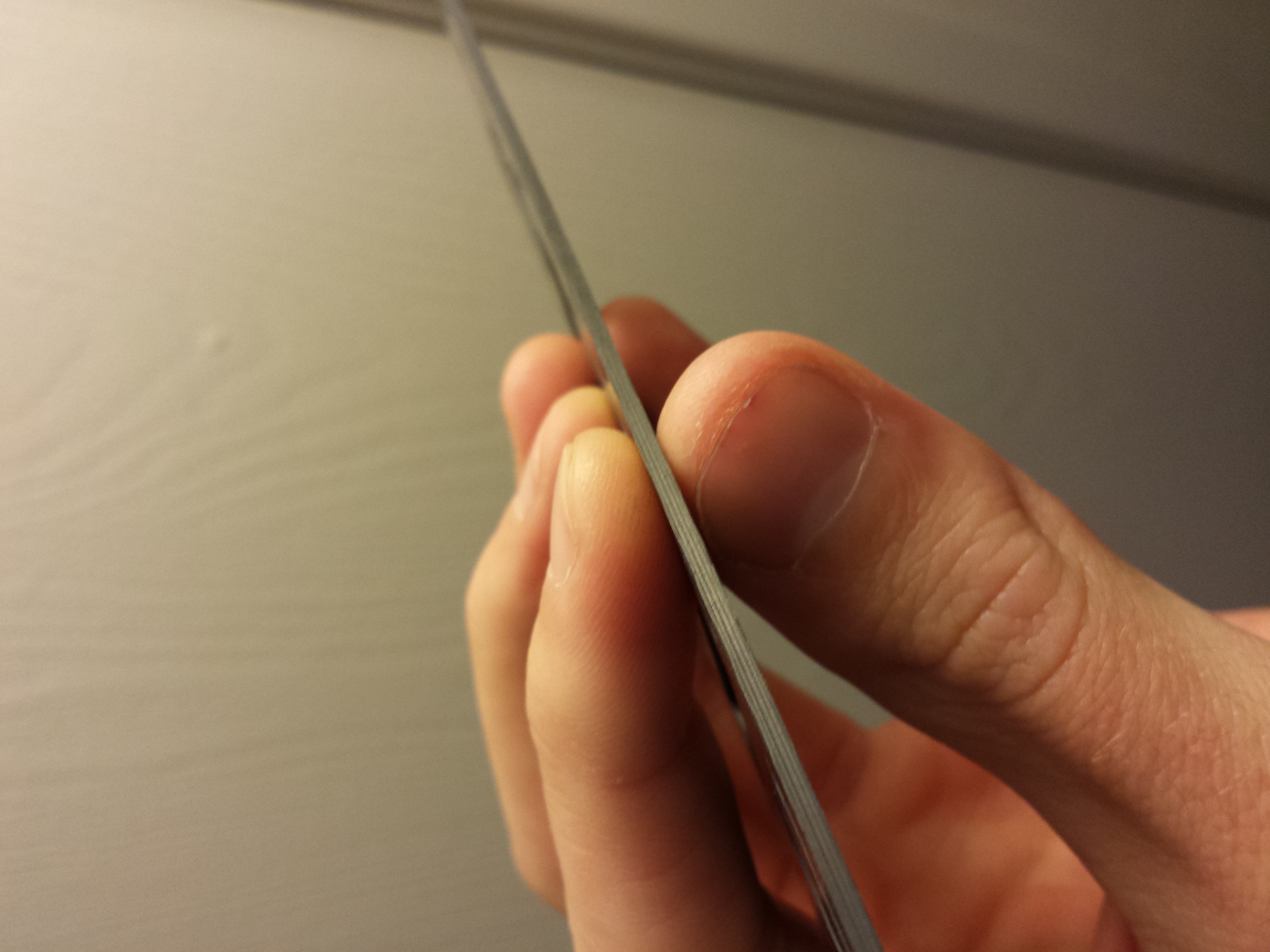
True carbon fiber conducts electricity. Luckily mine passed the test.
My build was based on the following parts:
- ZMR 250 Carbon Fiber Frame
- RCX 1804 2400kv Motors
- 12 A Mystery ESCs
- Naze32 Acro Flight Controller
- 1500 mAh 25C Lipo Battery
- Orange R110XL Satellite Receiver w/ CPPM
I will be adding the FPV gear in a later post with details on the wiring for that. All told, the parts came out under $200 USD not including the transmitter and miscellaneous wiring which I have from my previous builds.
Plan Your Layout:
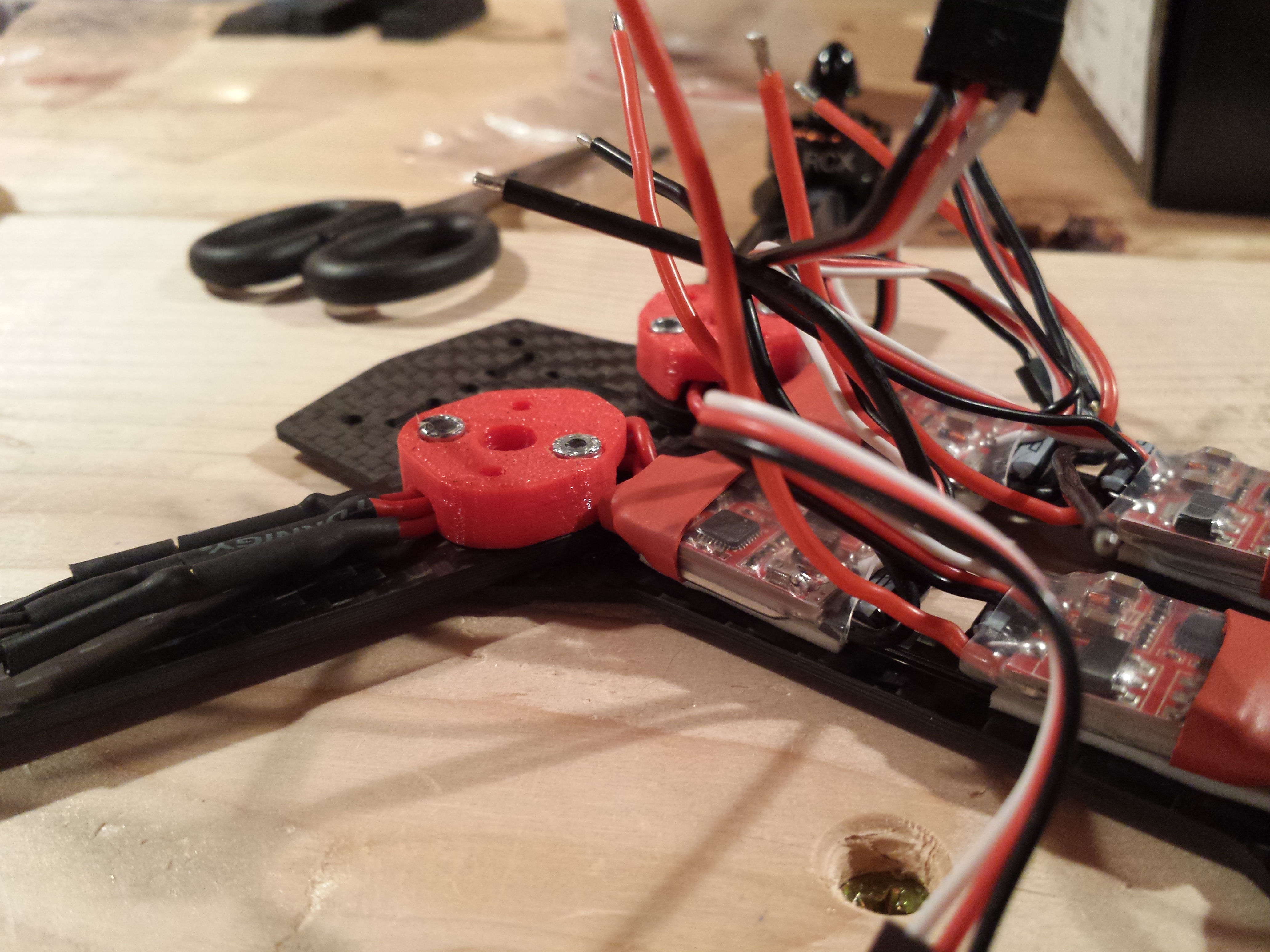
Moray’s spacer kit, modified by TheOne420, both of RCGroups forums, provide space between the two bottom plates to position components.
These 250mm class quadrotors are small. Even seeing pictures online, I was still surprised by just how compact everything is. After browsing through the forum posts, I chose the 3D printed spacers to position my speed controllers inside the frame. This cleans up the build in my opinion and keeps the ESCs well protected between the two frame plates. A word of warning however, carbon fiber is conductive so make sure that any electrical components are properly isolated during every step of the build. After fitting the ESCs and wiring under the spacers, everything is still quite a snug fit. You’ll notice I included double sided tape on the ESCs to keep them positioned squarely on the plate. This might not have been necessary once I added the top plate, but it helped with the initial wiring setup.
Power Distribution:
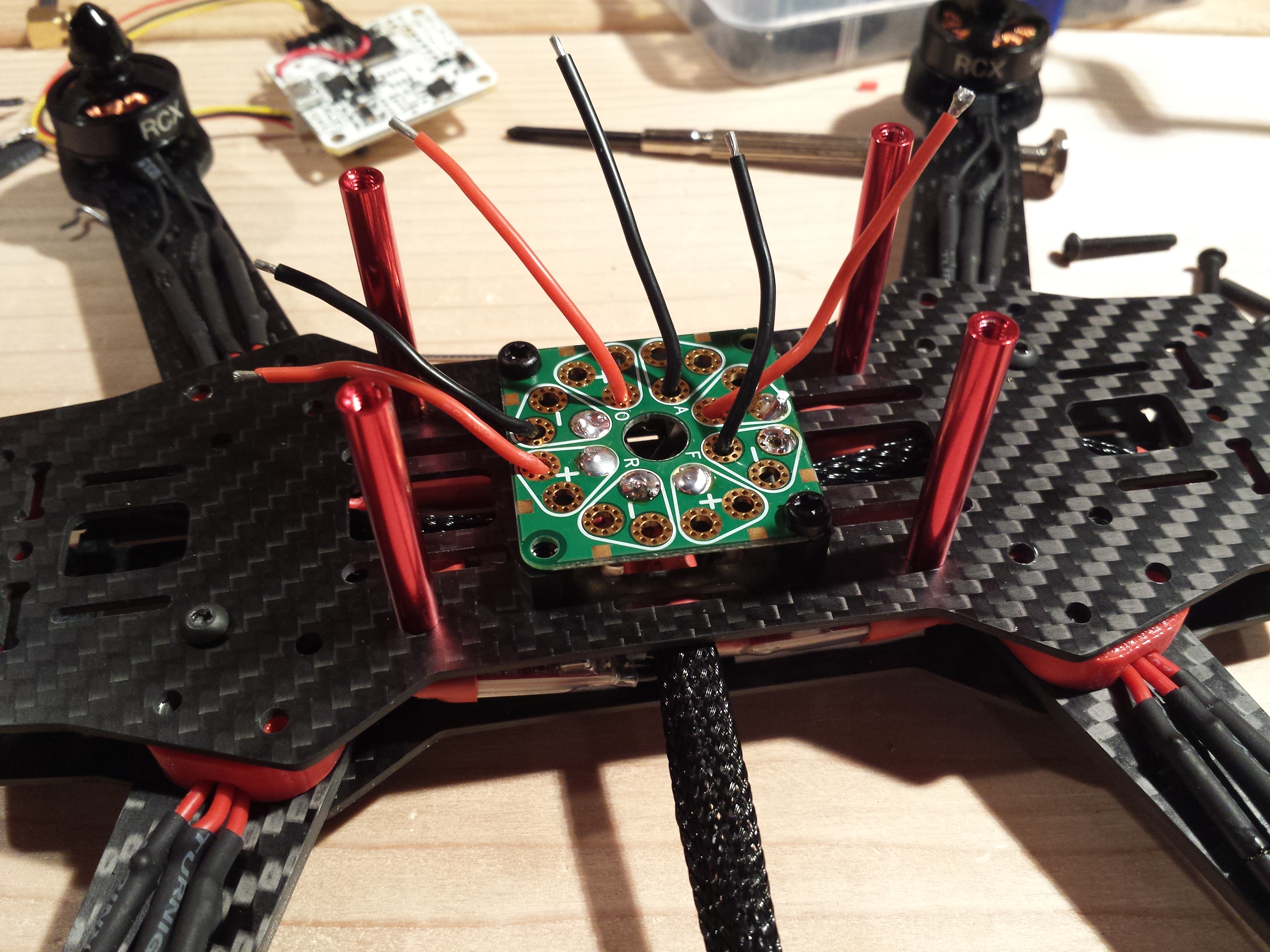
The power distribution board sits on top of the bottom half of the frame. The ESC and LED wires are routed through well placed holes in the plate.
One area of future improvement in my build will be the power distribution on this quadcopter. Initially I wanted to use a power distribution board as it simplified the layout while only adding a small amount of weight. In the future, I will rewire the quad with a wiring harness tucked in between the two bottom plates. This will also serve to lower the position of the Naze32 board which currently rests atop the PDB. For both the PDB and flight controller I used nylon standoffs for isolating the components.
After sizing up the wires for soldering to the PDB, I cut them to size and finished up the wiring of the lower unit. Here again I made sure to isolate the PDB from the flight controller by covering the top of the board with liquid tape which adds a thick rubberized coating to avoid short circuits.
Wrapping Up the Build:

The almost completed build. Flight controller and receiver have been added.
Once the power distribution was completed, the build progressed quite rapidly. Adding the Naze 32 was simple following this guide. (Note: I did not use a FrSky receiver.) The two insect antennae looking things on the top plate are the actual receiver wires placed alongside a ziptie and covered in heatshrink. This ingenious modification, dreamed up by FLDataTek at ModifiedRC.com, keeps the long wires out of the props while giving great signal coverage. No matter the orientation, you can see the wires when flying.
Some Random Improvements/Wisdom:
I don’t know if I can ever consider a build “complete” in the custom multirotor world. There are always new tweaks to cut weight or save space. That being said, I’m quite happy with the design but in the future I plan to continue this build with the following:
- Replace motors with 1806 2300kv (Ordered the wrong size!)
- Hardwire motors to ESCs and wrap with mesh. (Cleans up the build.)
- Wire in FPV transmitter and camera. (These are built for FPV after all.)
- Rewire the power distribution to save weight/space in between the top and bottom plates.
- Switch to a higher C battery, probably Nanotechs for top-end.
- Fly more!
Well that’s about it for now. Check back soon as I plan to put up a post working with the MinimOSD and FPV system.